MagProprio SoftHand
Maggie
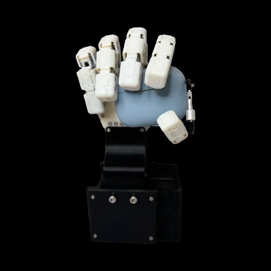
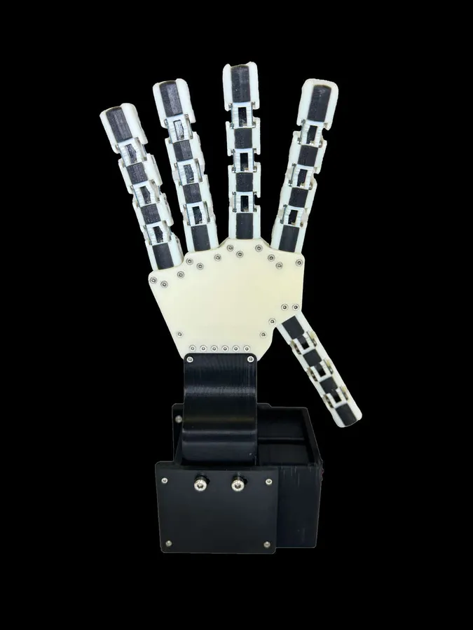
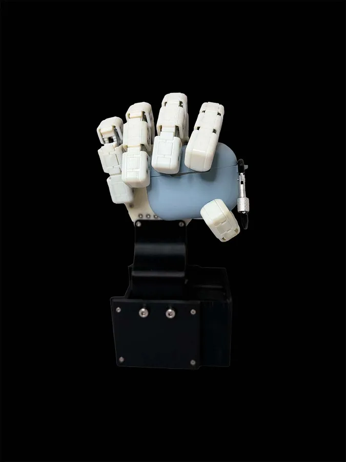
Maggie is a fully 3D-printed, anatomically accurate, highly underactuated, tendon-driven soft robotic hand with magnetic proprioception.
Designed and fabricated at the Bristol Robotics Laboratory in Bristol, UK, supervised by postdoctoral researcher Dr. Chris Ford and co-supervised by Prof. Nathan Lepora and Dr. Efi Psomopoulou.
Magnetic proprioception
Maggie's fingers are pulled by tendons, and two motors drive all five of them, one for flexion and one for extension. That keeps the hand simple, but the motor positions cannot tell you where each finger is: when the hand closes on an object, every finger stops wherever the object stops it. Proprioception gives the hand that missing sense of its own joint angles.
Each finger has three joints, and at each joint a linkage connects two geared phalanges. Two small neodymium ring magnets, 6 mm across and 1 mm thick, sit in every linkage, and a flexible PCB carrying an AS5070B magnetic position sensor wraps over the joint. As the finger bends, the magnet turns relative to the sensor, and the sensor reports that rotation as an angle. Five fingers with three joints each make fifteen sensors.
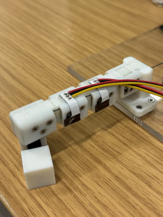
The flexible PCB
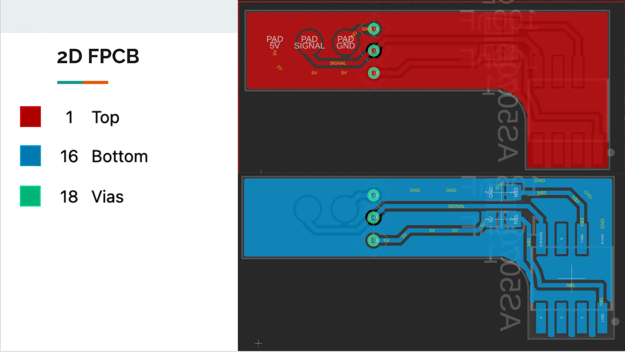
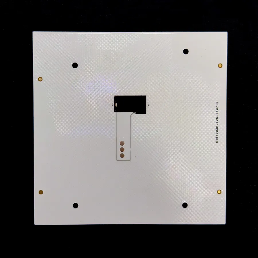
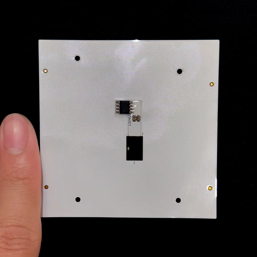
The first sensor I got reading, an AS5145B, was easy to talk to over SPI but needed eight pins and was too big for the smaller joints. The AS5070B needs only three connections, 5 V, signal and ground, so the board could become a thin strip that bends around the finger. I designed the flexible PCB in Fusion: two layers, the sensor at one end and three pads for a JST connector at the other.
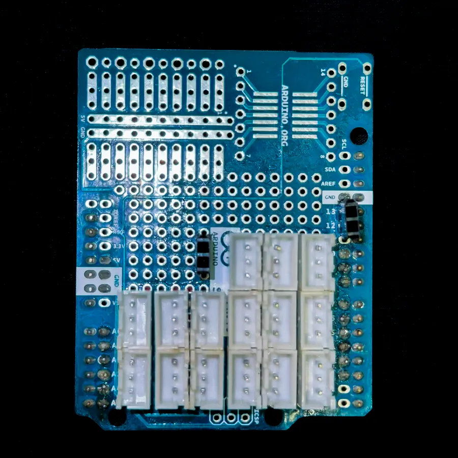
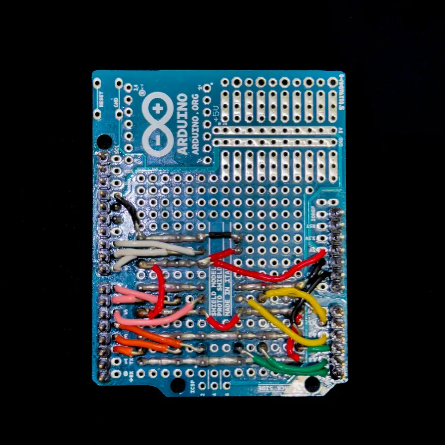
The fifteen sensors plug into an I/O board I designed and soldered on an Arduino shield, one 3-pin JST socket per joint on digital pins D2 to D19, plus TX and RX for the board that drives the motors. The first flexible PCBs had one mistake, a capacitor placed between 5 V and VCC that has to be bridged with solder. It is fixed in the schematic, but not yet in the layout.
From magnet to finger pose
The AS5070B is configured over a one-wire serial link that needs parity, and can then send its angle out as a SENT or PWM signal. With a lab colleague I wrote a library that sets it up: SENT or PWM output, the extended magnetic field range, the mechanical start and stop angles of a joint, about 60 degrees apart, and the transfer function between them. Decoding SENT on the Arduino, and reading PWM through an RC low-pass filter into an analog pin, both gave readings that did not follow the magnet, which pointed back at the configuration.
What read consistently was asking the sensor for its angle register directly. On start-up the code takes 50 readings of each joint at rest, discards the first 25 while the sensor settles, averages the other 25 as that joint's zero, and subtracts it from every reading after.
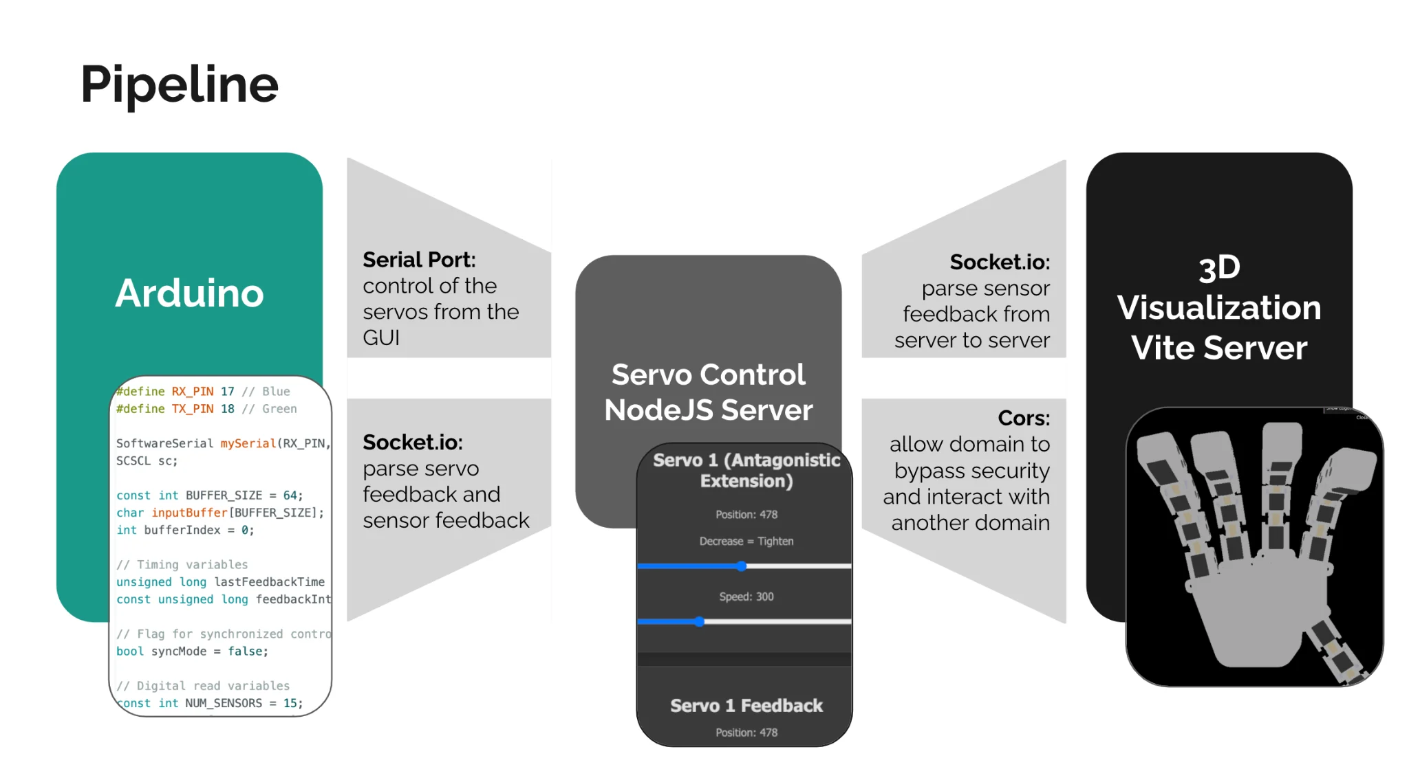
Three angles then place a finger. Because the phalanges roll on gears, each joint bends twice as far as its linkage turns, and the finger is rotated to its own angle on the palm. A Node.js server passes the angles over Socket.io to a Three.js model of the hand, a digital twin that moves with it. Malia Smith started the visualization, and I joined it to the motor control and the sensing.
By the end of the summer the pieces ran as one system: motor control from a browser GUI, joint angles read live from the flexible PCBs as a finger bends, and a digital twin that recreates the whole hand in 3D and moves with the angles the Arduino streams. The next step was reading all fifteen sensors at the same time, with a microcontroller that has more serial pins or with the sensor's SENT output.